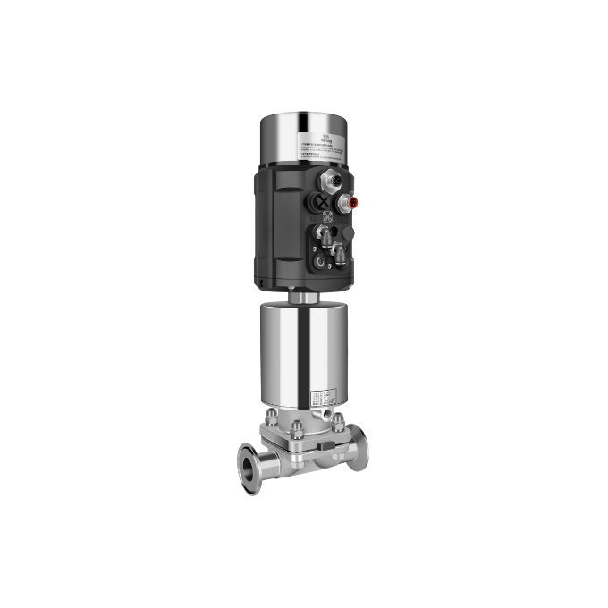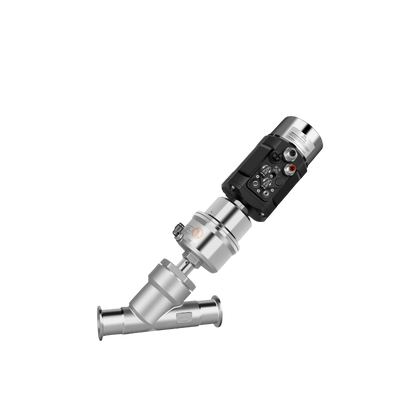
1600 series positioner is designed for integral pneumatic control valves, particularly suitable for angle seat valves and diaphragm valves.
The product is easy to operate and has rich software functions.
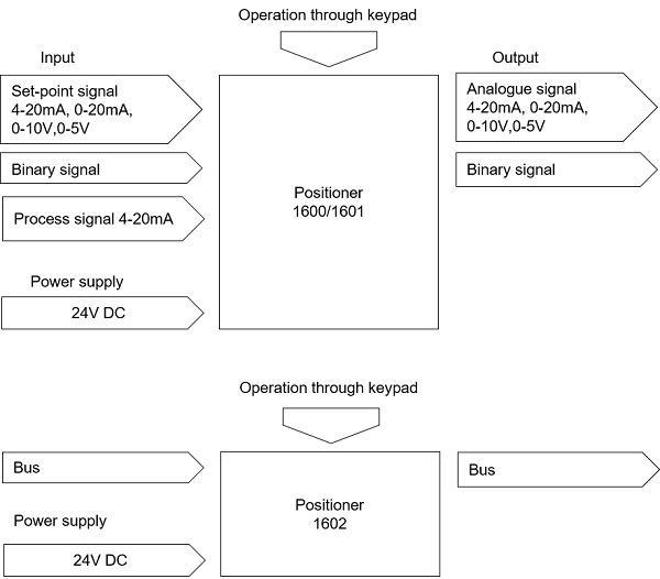
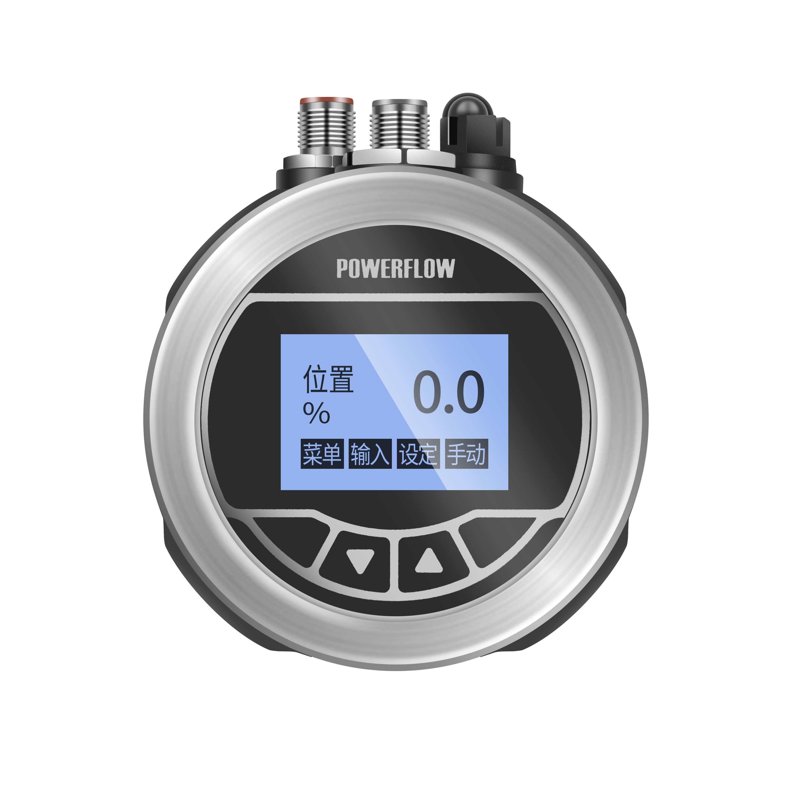
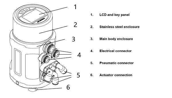
It can easily be operated via the LCD and keypad.
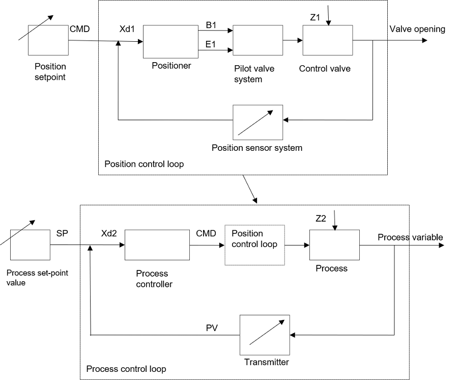
The positioner adjusts the valve position quickly and accurately through detecting the position sensor signal.


Without process control function(1600)
With process control function(1601)
Without process control function (Profibus-DP)(1602)
Without feedback signal(N)
4-20mA feedback signal(Y)
Single-acting(S)
Double-acting(D)
Linear 5-25 mm(S2)
Linear 25-50 mm(S3)
Rotary 90°(S4)
17 L/min(Q1 )
58 L/min(Q2 )
G1/4(T1 )
M16 * 1(T2)
M22 * 1.5(T3)
M26 * 1.5(T4)
Fail-safe(S)
Fail-freeze(F)
In the air flow rate option, code Q1 is suggested to match the actuator of 40-100 mm internal gas chamber diameter, code Q2 is suggested to match the actuator of 125-160 mm internal gas chamber diameter. Code Q2 is only used for single-acting actuator, and only in Freeze state when power-off. The air flow rates for code Q1 and Q2 are under the condition of 0.6Mpa input pressure.
In the valve max stroke option, AT actuator range for code S4 is AT50~AT125. For other actuator types, please consult our company. It is no need to select the thread type option for code S4.
Power off state for single-acting option is Safe by default.
| Material | PC, SI, PA6-GF30, SS304 |
| Power Supply | 24V DC±10% |
| Input signal(1600/1601) |
0/4 - 20mA or 0 - 5/10 V |
|
Input resistance for input signal(1600/1601) |
240Ω at 0/4-20mA 20KΩ at 0-5/10V |
|
Control medium Dust concentration Particle density Pressure condensation point Oil concentration |
neutral gases, air DIN ISO 8573-1 Solid particle size and density Class 3 Dew point Class 3 Oil content Class 3
|
| Ambient temperature | 0-60°C |
| Pneumatic connection | Plug-in hose connector G1/4(internal Φ6mm) |
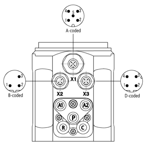
| Electrical connection |
M12 3-pins B-coded(cable ø 4-6mm) M12 4-pins D-coded(cable ø 4-6mm) M12 5-pins A-coded(cableø 4-6mm) |
| Supply pressure | 3~7 bar, specific values depending on the actuator |
| Air flow rate |
17 L/min(input pressure of 0.6Mpa) 95 L/min(input pressure of 0.6Mpa, only single-acting) |
| Stroke control range |
Linear 5-50mm Rotary 90° |
| Installation | As required, Preferably with actuator in upright position, Screw |
| Protection class | IP67 |
| Power consumption | <5W |


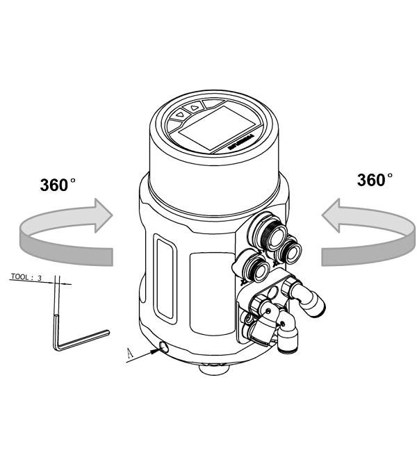
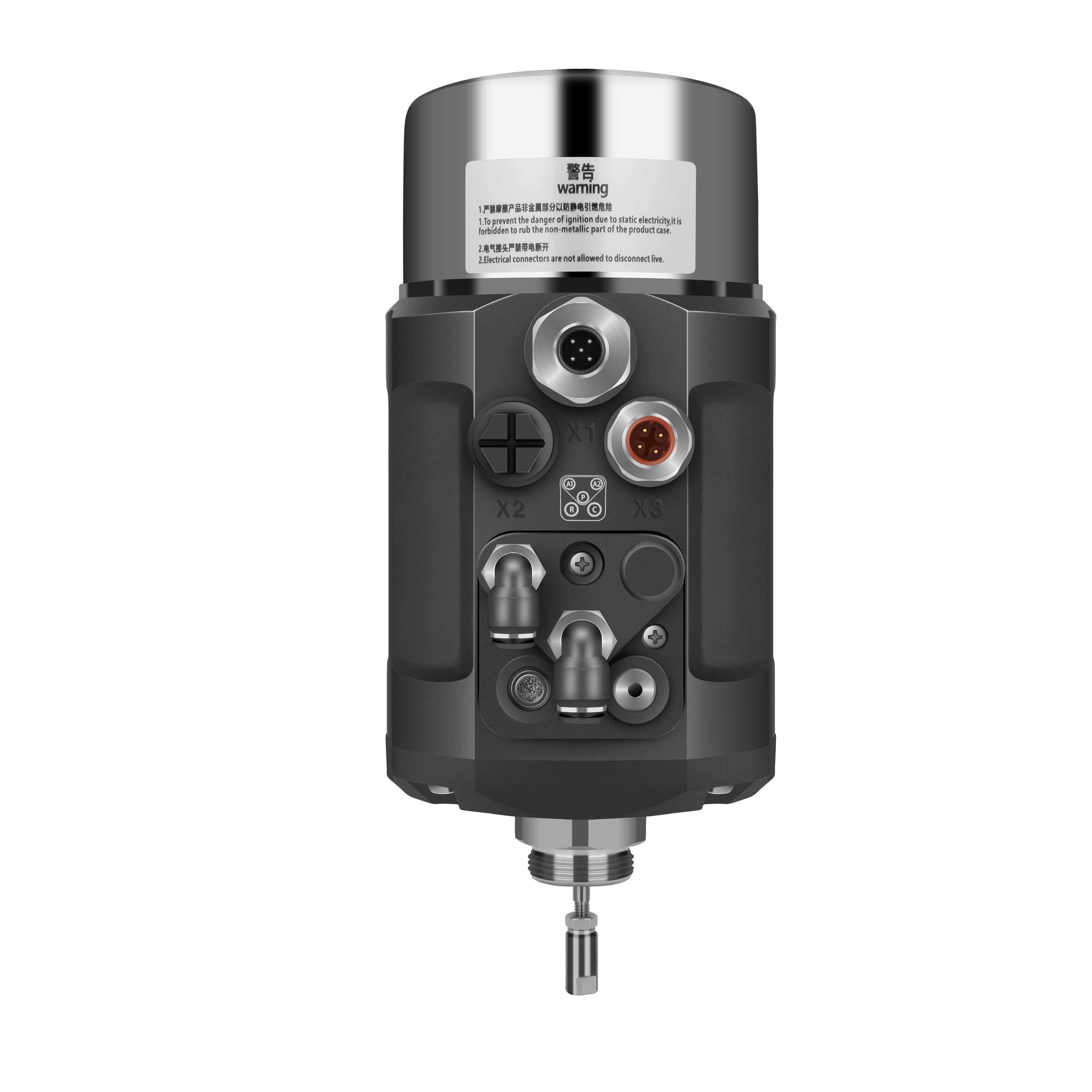
The angle can be adjusted between the positioner and the valve. If need to adjust the interface angle, relaxing the hexagon screw in place A first. Then adjusting the angle clockwise or counter-clockwise in 360°range. After adjusting the angle, locking the angle by the hexagon screw.
X2 (1601)
Transmitter input +
+24 V
Transmitter signal output
4-20 mA
Transmitter GND
GND
0/4–20mA or 0–5/10 V
X1 (1600/1601)
Analogue signal output +
0/4–20mA or 0–5/10V
Binary signal output 1
0/24 V
Binary signal output 2
0/24 V
Binary signal input +
0-3V =”0”,15-30V =“1”
Signal common GND
GND
X1 (1602)
Bus power supply +5V
/
B Inverting driver output/receiver input
/
A Non-inverting driver output/receiver input
/
DE Driver enable status output
/
Bus GND
/
| P | Air supply enter(built-in filter, filter size 5 μm) | |
| R |
Air exhaust |
|
| C |
Check valve |
|
|
A1 |
Pilot air outlet 1 |
|
| A2 |
Pilot air outlet 2 |
|