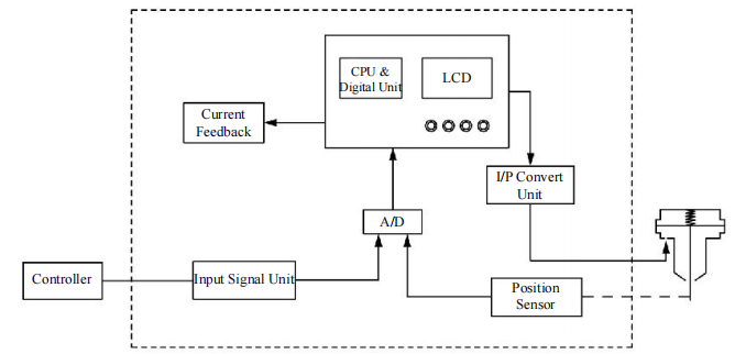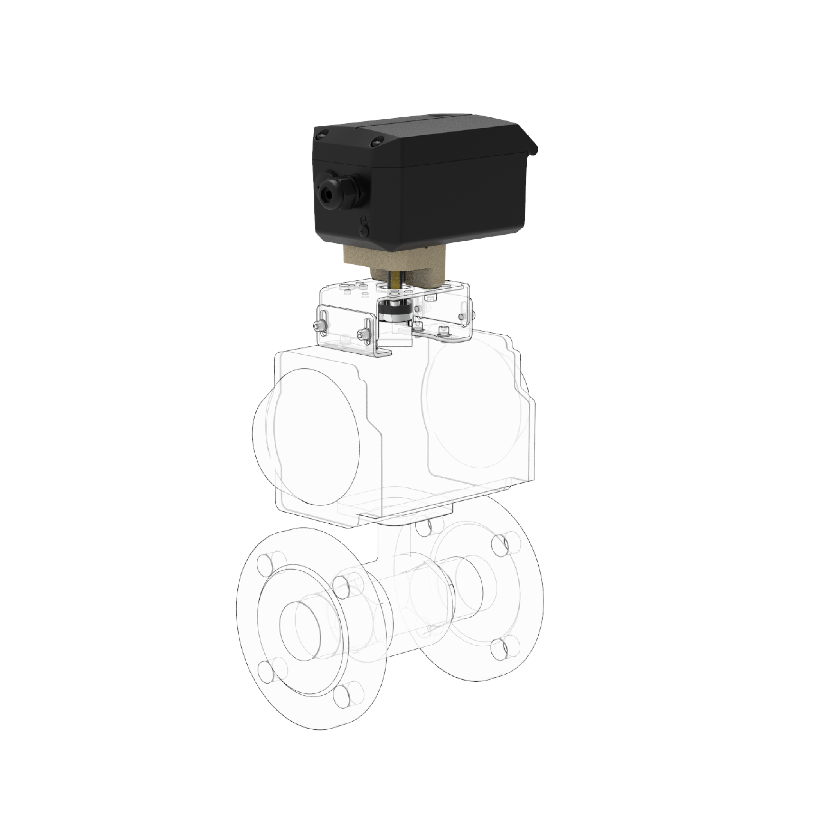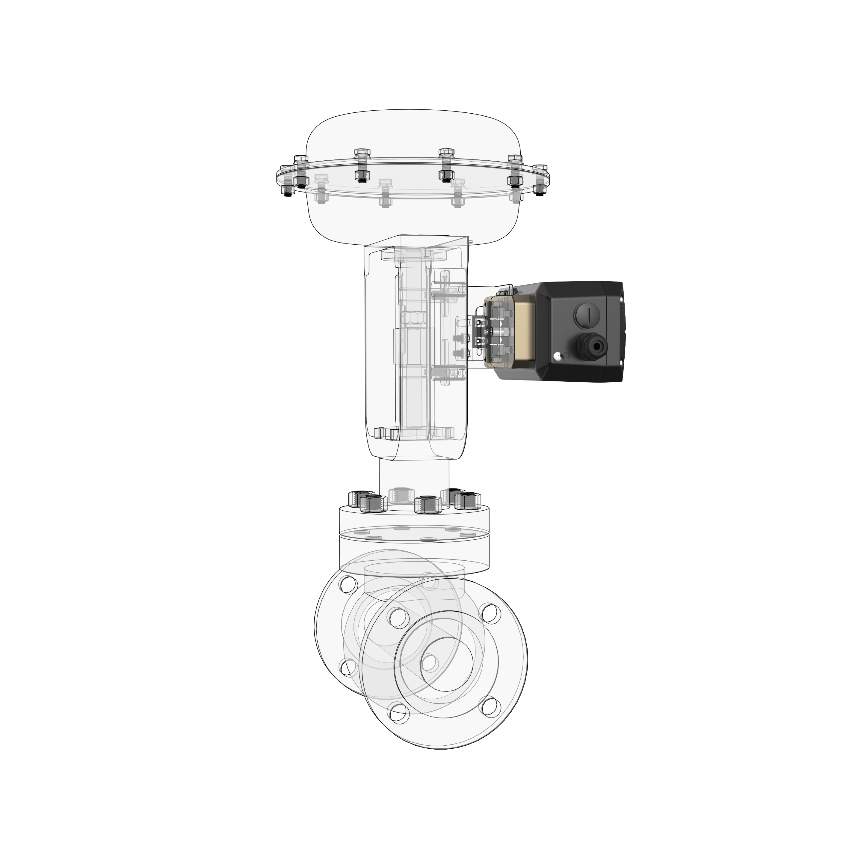
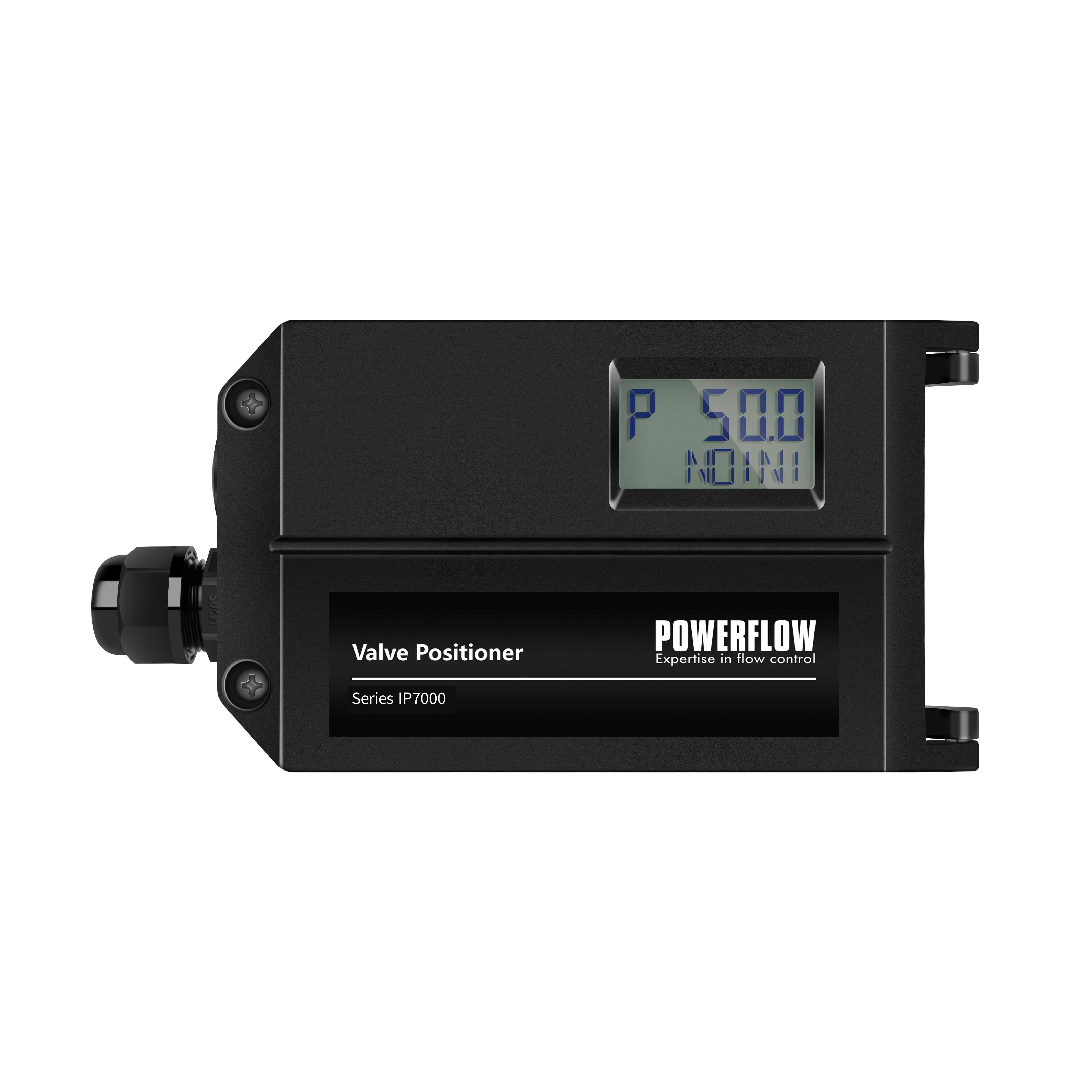
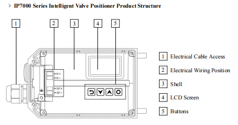
IP7000 intelligent valve positioner is mounted on pneumatic control valves.
It’s used to control air intake and exhaust of the pneumatic actuators to drive the valve position to the set point by calculating both data from 4-20mA DC signal and feedback position.


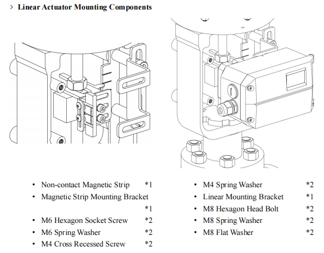
Normal linear(L)
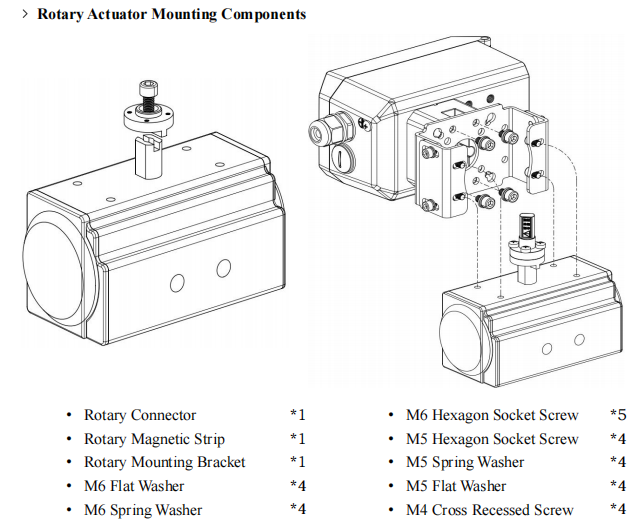
Normal rotary(R)
Single acting(S )
Double acting(D)
Non explosion(n)
Ex ia IIC T4/T6 Ga( i)
Ex ia ⅢC T200 135℃/T200 85℃ Da(i)
No(0)
Yes(1)
No(0)
Yes(1)
No(0)
Linear(1)
Rotary(2)
No(0)
Yes(1)
Safe(S)
Freeze(F)
-20℃(N)
-40℃(L)
|
Enclosure material |
Aluminum, powder coating |
| Pressure gauge block material |
Aluminum, anodized |
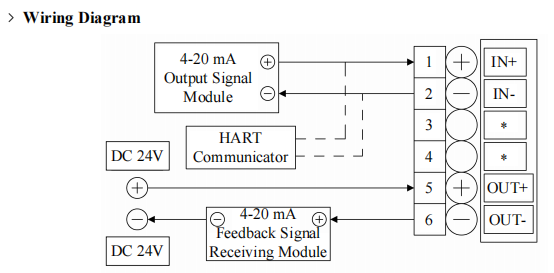
| Input signal |
Current: 4-20mA DC
No-load Voltage: 15-24V DC Input Resistance: 120Ω |
|
Output signal |
2-wire 4~20mA signal |
| Digital communication protocol |
HART 7 |
| Minimum operating current |
3.8mA |
| Steady state air consumption |
≤ 0.4 L/min |
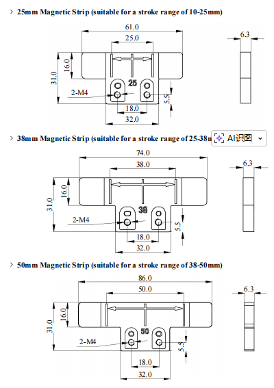
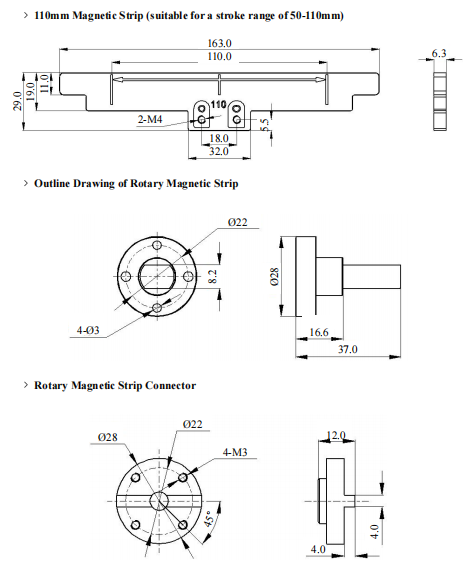
| Stroke range |
Default linear type: 10~110mm Default rotary type: 80~100° |
| Pneumatic data |
Air quality meets ISO 8573-1 standard Pressure range: 1.4~7bar(20.3~101.5psi) Solid particle size and density: Grade 3 Pressure dew point: Class 3 (minimum 20K (36°F) lower than the ambient temperature) Oil content: Class 3 |
| Vibration resistance |
0.15mm, 10Hz-60Hz, 20 cycle/axis 20m/s2, 60Hz-500Hz, 20 cycle/axis Recommended range for control valve≤20 m/s2, no resonance peak |
| Electrical connection |
NPT 1/2 (default) M20×1.5 |
| Pneumatical connection |
NPT 1/4 (default) G1/4 |
| Protection class | IP69 |
|
Basic error & Hysteresis error |
≤ 1% |
| Ambient temperature |
Normal Version for Non-explosion- proof: - 20℃ ~ + 80℃ Low Temperature for Non-explosion-proof: - 40℃ ~ + 80℃ Ex ia Default Type: - 20℃ ~ + 80℃ (T4/T200 135℃) - 20℃ ~ + 40℃ (T6/T200 85℃) Ex ia Low Temperature Type: - 40℃ ~ + 80℃ (T4/T200 135℃) - 40℃ ~ + 40℃ (T6/T200 85℃)
|
|
Explosion-proof grade |
Ex ia ⅡC T4/T6 Ga Ex ia ⅢC T200 135℃/T200 85℃ Da |
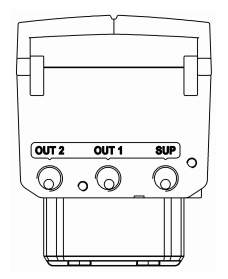
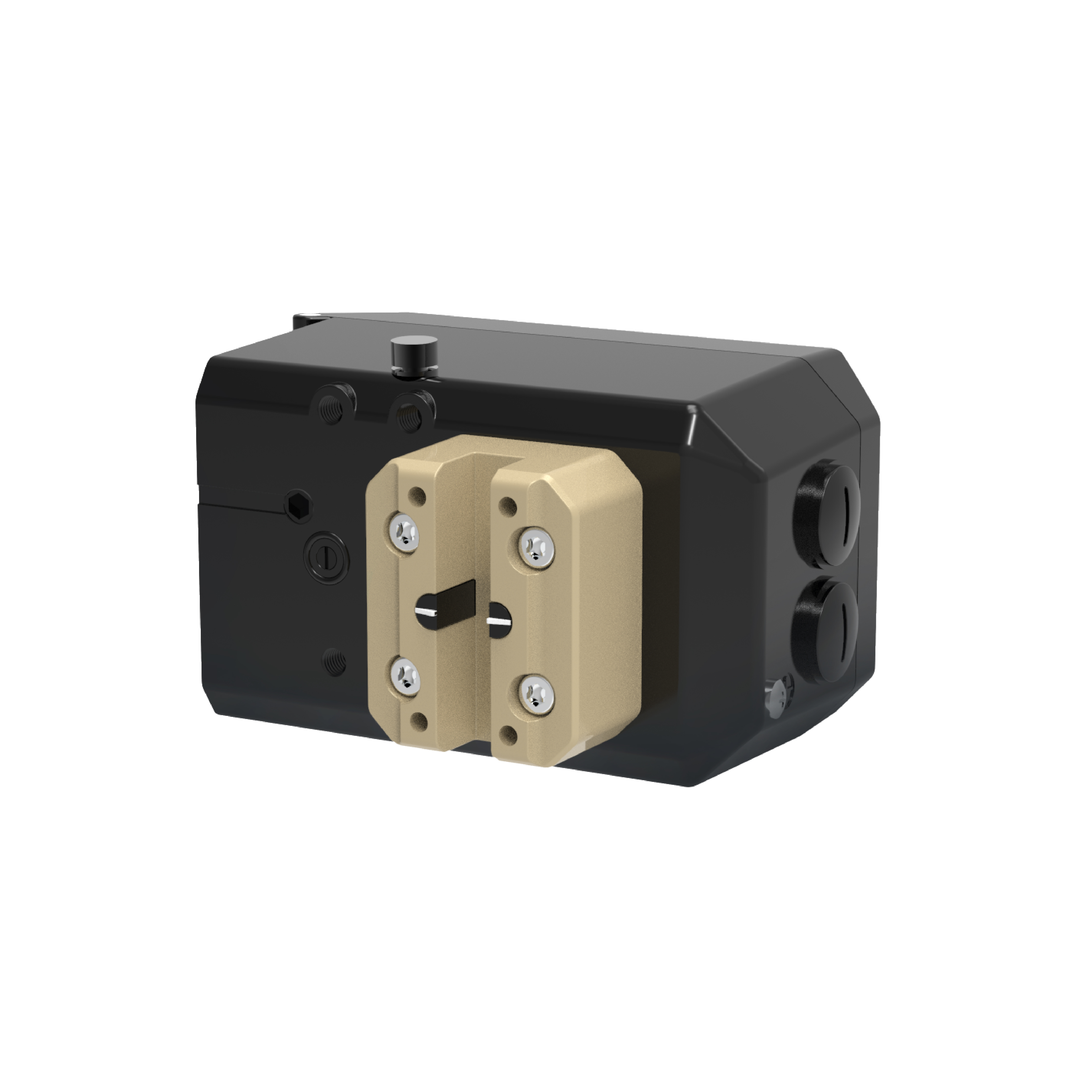
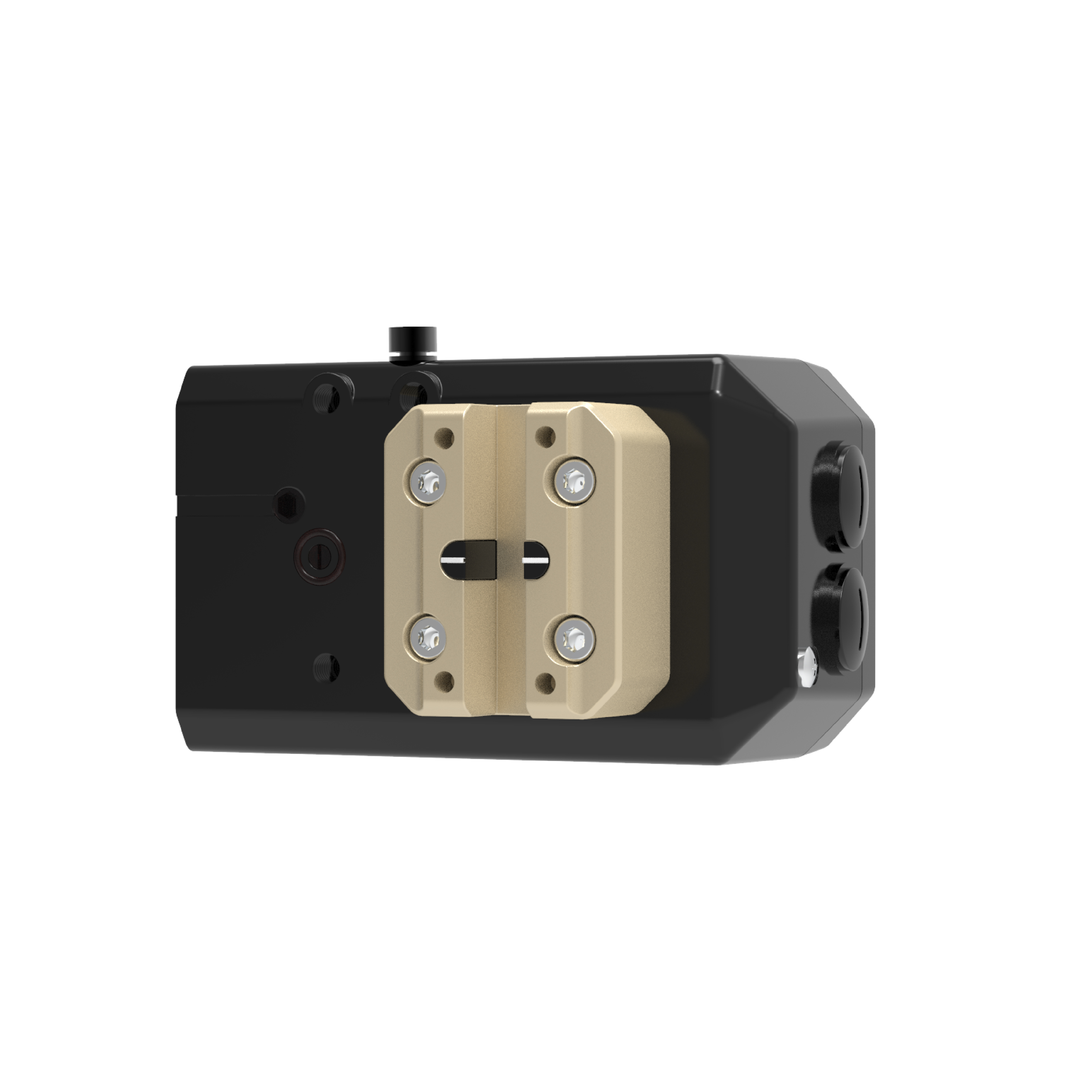
Air
supply input
Pilot air outlet 1
OUT2
Pilot air outlet 2, used for double acting type
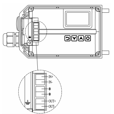
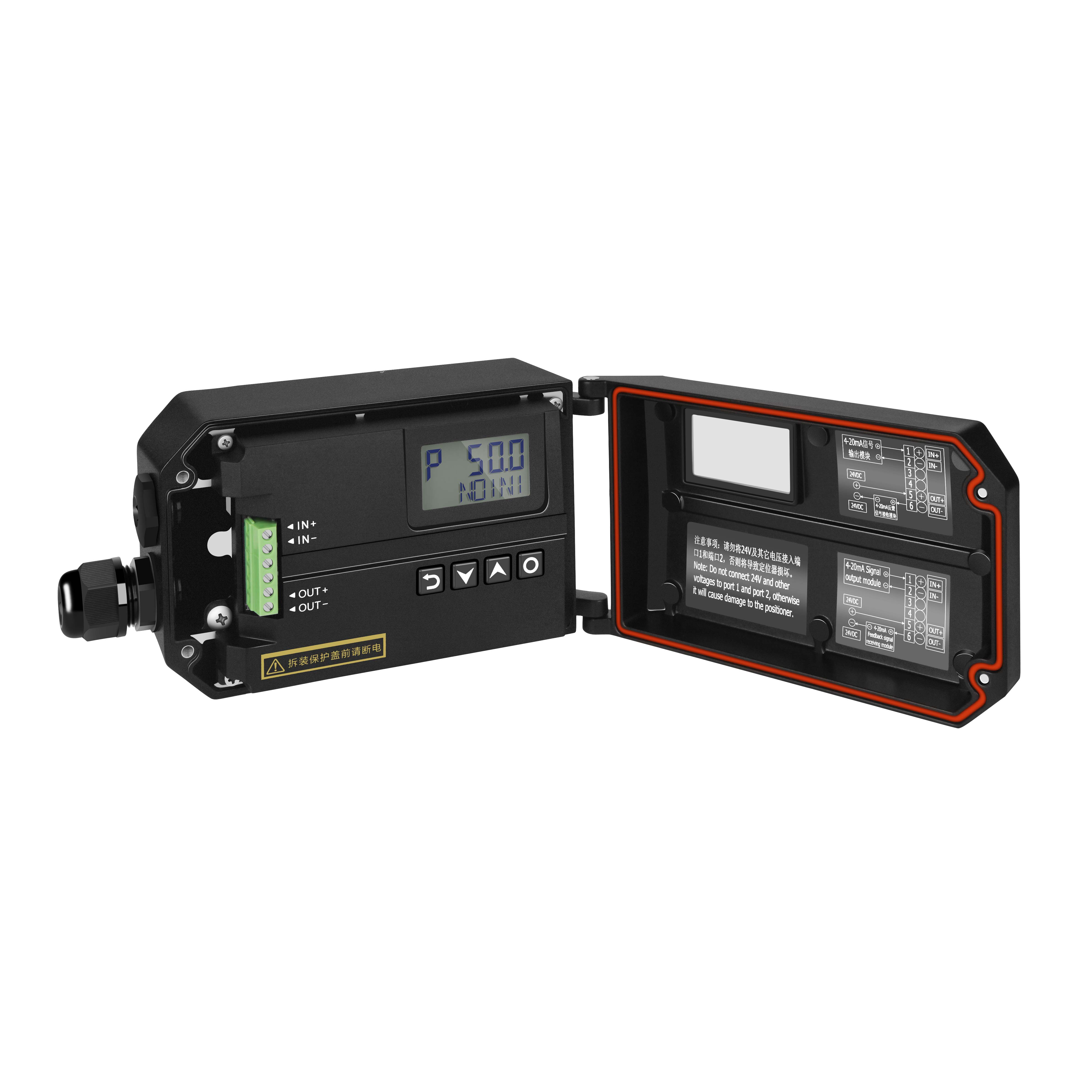
OUT+
OUT-
*
The two interfaces are connected with each other, and the device is in low impedance mode